Introduction
A gear system is designed to transmit angular movement between two axes. The size ratio of the gears determines the force/speed transfer ratio. An ideal system is composed of two wheels with a touching point that doesn’t slip. Real gears have teeth to avoid slippage, and the main design criteria is the constant transmission of force.
Gears are simple and efficient in applications involving low velocity and high torque. The basic gear profile is called Spur and has teeth parallel to the axis.
The tooth profile is designed so that the force vector is always perpendicular to the face of the tooth. This is accomplished using an involute curve. This course is generated by unwinding a string from a cylinder. The curve described by the tip of the string is the involute.
Construction of the involute
The string OAB unwinds from the circle of radius R. At the point A the segment AB is tangent to the circle, and perpendicular to the involute.
 The involute can be described parametrically with reference to the angle


The circle of radius r is called the Pitch circle and is the idealised contact point between two gears.
Pressure angle
Two complementary involutes touch at a point that slides along the curves as the gears rotate. In order to ensure a smooth transference of force, the force vector should always be perpendicular to both curves at this point. This vector is called the Action line, and for practical reasons it has a small offset from the line tangent to both Pitch circles.
This offset is called the Pressure angle, and is typically 20 degrees. Other values are 14.5 and 25 degrees.

Applying a Pressure angle 


Note that the Pitch circle remains the same.
Tooth size and profile
The size of the tooth depends on the number of teeth and the Pitch diameter. The tooth size must be the same for matching gears and is called Module.

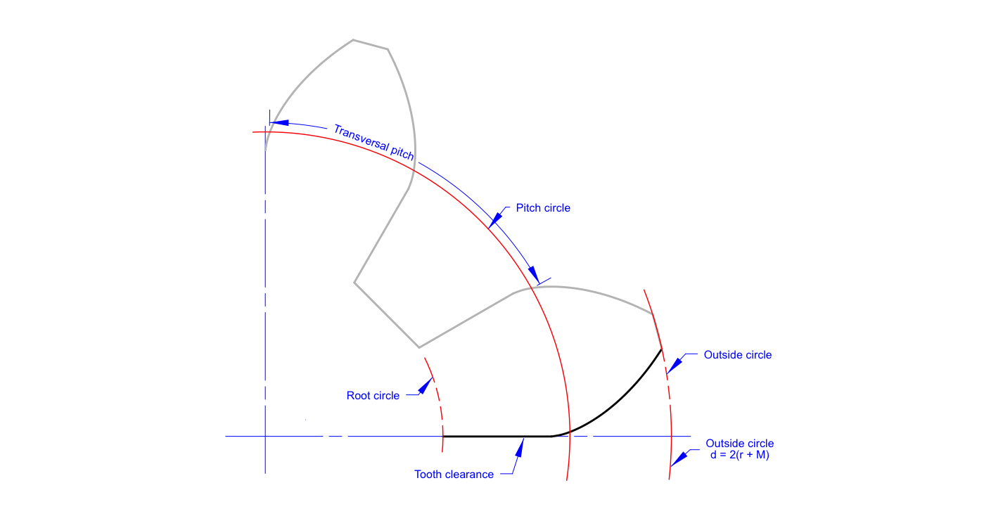
The distance between two teeth, which is the length of the arc between two similar points is called Transversal pitch and given by:

The tooth is delimited by the Root circle and the Outside circle. The diameters of these two circles are defined by the following equations:


The final tooth profile is drawn with a spline and a few lines. This can be easily drawn on any CAD program and manipulated into any image for convenience.